Alan's Home Page
Temperature sensors need to be shielded from direct radiation otherwise an incorrect temperature could be indicated. If the sun is shining on the sensor then it would likely read higher than the actual air temperature.
Alternatively if the sensor is exposed to the night sky then it would likely read lower than the actual air temperature.
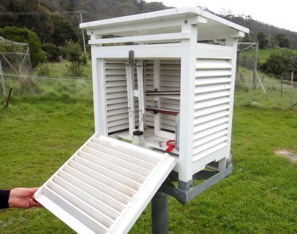
To overcome this radiation problem "official" temperature sensors are shielded by a "Stevenson Screen". This is usually a white-painted wooden box with slatted sides for ventilation. Unfortunately these boxes are rather too large to be included with the average home weather station.
Typically a home weather station is supplied with a rather rudimentary screen which would be OK if the station were placed in a shaded position such as under the eaves of the house. However such a position is impractical if the station is also meant to obtain accurate rain and wind readings.
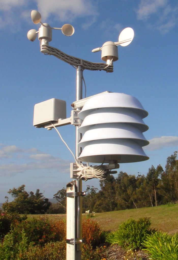
At left is shown a Maxkon weather station to which a home-made "Stevenson Screen" has been added.
The screen is made from 4 melamine bowls held together with threaded rod and tubular spacers. The bowls can be obtained for about $1.00 each if you find the right kind of shop. (For best performance the bowls should be white both inside and out).

Buying List:
1. Four white melamine bowls 200mm dia x 50mm deep.
2. M6 galvanized threaded rod, 450mm long.
3. M6 galv. nuts and washers, 7 of each.
4. Aluminium tube, 10 (or 12) mm dia, 400mm long. (Instead you could use stainless steel tube or even stiff plastic tube).
5. Galvanized RHS, 25mm square, 200mm long.
6. M6 galvanized bolt, 35mm long.
 Method:
1. Using a hole saw make a 50mm hole in the centre of 3 of the bowls. (The 4th bowl will be the lid and should not have a hole).
2. Now, on a pitch-circle-diameter of about 90mm drill 3 equally spaced holes at 6.5mm diameter into each of the 4 bowls. (You could possibly do this with the bowls stacked together).
3. Next cut the tube into 9 pieces at 40mm long. (This length will ensure about the right amount of vertical overlap between the bowls).
4. Cut the threaded rod into 3 pieces at 150mm long.
5. Thread the whole assembly together as shown in the pictures (left) and fasten each rod with a nut and washer at the top and bottom ends. (Nylon nuts, as shown in one of the pictures, could be used in lieu of galv. nuts).
 Mounting Arm:
(The mounting arm described below will suit a weather station with a 20mm dia pole).
1. Cut the RHS to 200mm long.
2. One end is to be made into a split clamp as follows: Drill a dia 20mm hole 22mm from the end.
3. Drill a dia 6.5mm hole 6mm from the end and at right angles to the axis of the first hole.


4. With a hacksaw or an angle grinder, slit the RHS as shown in the picture.
5. The outer end of the mounting arm will look much neater if a piece is cut out such as to allow the top flap to be bent down and make an enclosed end. (See pictures at left).
6. The arm can be attached to the top melamine bowl with 2 screws (say M5) tapped into the bottom side of the RHS.
You will need to work out the positions of these screws such as to give the correct radial position for the screen assembly. (For the Maxkon station the radial distance from the centre of the mounting pole to the centre of the screen assembly is 160mm).
Accuracy:
Readings from this weather station have been compared with official local weather bureau temperatures and also with 2 other (well shaded) sensors and good agreement was found, leading to the conclusion that "radiation errors" are likely to be less than 2 degrees Celsius (mostly less than 1 degree). (Errors with the original "as supplied" screen sometimes exceeded 5 degrees Celsius).
Note: The shield descibed above does not shield the radiation coming from the ground. Thus it is best if the ground underneath is grassed or covered with something that has low emissivity.